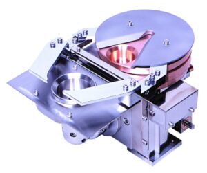
Electron beam sources are a primary evaporation tool for depositing materials used in optical coatings applications at wavelengths from UV to IR. High deposition rates are achieved for fluoride and oxide compounds, metals, and single element materials. Compared to resistance-heated evaporation, E-guns require high voltages and currents, thus commanding special operating and maintenance practices.
Electron Beam Gun Maintenance Drives Coating Yield
Producing the evaporation beam energy requires high kilovolt and ampere supply levels. Build up and contamination can lead to arcing. Avoiding beam drilling and consequent rate changes while ensuring uniform deposition coverage requires sweeping the beam over the material charge in the crucible.
Magnet alignment after a cleaning procedure is crucial to maintain continuous production yield. The hot filament that enables thermal electron emission has a limited lifetime. These are some of the considerations that necessitate periodic maintenance of electron beam sources.
Physical vapor deposition sources deposit material on hearth assemblies, shielding components, and tooling surfaces. In addition to producing potential sources of particulate matter, material coated on high-voltage insulators can lead to arcing and unstable deposition rates.
This continuous accumulation shifts spatial beam positioning, degrades emission stability, and forces closed-loop rate controllers into unstable oscillation.
Contamination that bridges high-voltage insulation gaps can initiate destructive arc events that inject micro-particulates into growing thin films. Within precision optical manufacturing, particulate contamination triggers immediate batch rejection and extensive requalification protocols.
Deposition uniformity relies heavily on consistent gun geometry because spatial drift alters vapor plume distribution. While advances in e-beam source technology have improved magnetic stability and crucible longevity, systemic hardware reliability depends entirely on rigorous preventative intervention.
A Step-by-Step Cleaning Routine for Electron Beam Sources
Most production environments execute intermediate inspections weekly and exhaustive overhauls monthly, though high-deposition-rate metal processes demand increased frequency.
Suggested sequence during every maintenance window:
- Vent the vacuum vessel and confirm electrical isolation by grounding the high-voltage bus with a dedicated manual discharge hook prior to contact.
- Extract the thermal radiation shield and internal hearth liner, examining both structural elements for stress fracturing, dimensional warping, and heavy film accretion.
- Decontaminate metallic shields via precision bead blasting, maintaining strict exclusion zones around vacuum sealing interfaces and magnetic pole pieces.
- Remove residual evaporation material from the crucible pocket to eliminate thermal barriers that inhibit conductive cooling and induce metal cracking.
- Clean internal gun bodies using laboratory-grade isopropyl alcohol and low-lint wipers, ensuring complete solvent evaporation prior to mechanical reassembly.
- Inspect internal cooling channels for mineral scale buildup or localized flow restriction, which serves as a primary catalyst for thermal failure.
- Verify permanent magnet placement and sweep coil terminal integrity before sealing the deposition chamber.
Record every cleaning procedure within facility maintenance logs. Historical tracking exposes degradation trends long before single inspections reveal structural flaws, aiding troubleshooting.
Inspecting High-Voltage Insulators and Feedthroughs
Ceramic dielectric components undergo gradual surface degradation prior to total electrical breakdown. Internal alumina standoffs collect microscopic conductive films that appear benign under ambient inspection yet facilitate high-voltage breakdown under operational loads exceeding 10 kV.
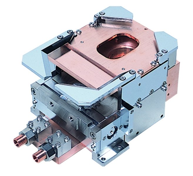
- Examine insulators under intense illumination, checking for surface discoloration, micro-fracturing, and carbon tracking branches.
- Replace compromised ceramics immediately because solvent cleaning cannot restore structural dielectric properties.
- Inspect high-voltage feedthrough connections for collar contamination and terminal pitting. Loose electrical interfaces generate localized resistance heating that carbonizes adjacent support hardware and creates a conductive path.
- Verify correct torque specifications across all terminal fasteners.
- Validate circuit isolation using a high-resistance megohmmeter prior to initiating critical production runs.
- Measure baseline resistance between the filament current circuit and chassis ground while components remain cold and dry.
Decreasing resistance trends indicate progressive contamination before arcing interrupts production. Systems engineered to strict military and international durability standards yield maximum reliability when paired with this verification methodology.
Filament Replacement and Arc-Over Prevention
Tungsten emitters are consumable resources requiring a replacement schedule based on accumulated operational hours to prevent structural breakage during a run. Material sublimation reduces wire cross-section over time, altering emission intensity and failure. The deposition of oxide compounds accelerates replacement intervals.
Signs that warn of impending failure:
- Emission current demands constant upward adjustment to sustain deposition rates.
- Visible beam trajectory wandering or spot localization failure occurs.
- Minor electrical arcs repeatedly manifest during initial power ramping.
- Unprovoked deposition rate spikes appear without power input adjustments.
Handle replacement filaments exclusively with lint-free powder-free gloves because residual skin oils create localized hot spots that shorten operational lifespan. Align replacement components precisely to manufacturer dimensional specifications because minor placement errors distort electron optics and landing coordinates.
Post-replacement procedures require complete vacuum evacuation followed by a controlled thermal conditioning ramp. Gradual power escalation outgasses newly installed hardware and barks bake off residual contaminants. Omitting this conditioning phase remains the primary catalyst for immediate post-maintenance arcing.
Legacy systems often arc because their control hardware cannot respond fast enough. Modern arc suppression circuitry detects and quenches events in milliseconds. Tecport Optics designs and builds custom vacuum coating systems with that kind of protection engineered in from the start. Existing chambers can also gain the same capability through retrofit and upgrade services, including updated power supplies, sweep control, and plug-and-play automation.
Sustaining Coating Production Schedules
Rigorous maintenance protocols safeguard production deadlines, qualification metrics, and operational profitability. Tecport Optics provides comprehensive support for coating facilities through complete system integration, process optimization, operator training, and replacement component inventory.
Our technical team assists manufacturing operations in converting reactive repairs into structured service intervals while delivering fully configured turnkey systems rapidly following site arrival.
Contact our engineers about electron beam source support and system upgrades by reaching out to Tecport Optics today.
Frequently Asked Questions
What compatibility risks emerge when utilizing third-party filaments within industrial electron beam evaporators?
Aftermarket components frequently exhibit dimensional variances in wire gauge and forming tolerances. Minor geometric deviations alter electron emission dynamics and flux distribution. Validate alternative supply sources through non-controlled trial runs prior to production deployment.
How does cooling water quality impact the operational lifespan of deposition hardware?
Unfiltered mineral content precipitates scale inside restricted copper cooling channels, severely limiting thermal transfer efficiency and causing structural hearth fractures. Deploy closed-loop cooling systems utilizing chemically treated water and measure fluid conductivity quarterly.
Which storage environment best prevents oxidation in spare tungsten filaments and hearth liners?
Store components sealed within original packaging inside a desiccant-regulated dry cabinet to eliminate humidity-induced surface oxidation. Handle spare inventory exclusively with clean protective gloves during extraction.
How frequently should operators recalibrate beam sweep patterns during routine system maintenance?
Magnetic deflection patterns drift over time due to thermal cycling and mechanical wear within crucible pockets. Verify beam positioning against a clean crucible charge quarterly and adjust deflection parameters accordingly.