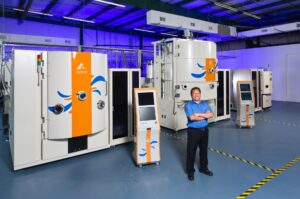
A production run containing many small substrates or one large substrate requires good deposition area uniformity. Single axis rotation for the largest substrates or planetary axis rotation for many small substrates experience thickness roll-off due to the profile of the evaporant plume that can be as large as a few percent.
Customer requirements for uniformity over a diameter can be as tight as 0.5% or better to produce performance within stated tolerances. Specialized tooling mechanical motion and orientation is employed to achieve the required uniformity. Steeply curved or angled substrates require special tooling configuration beyond flat substrate geometries.
Root Causes of Uniformity Breakdown
Every physical vapor deposition source, whether thermal evaporation, e-beam, or sputtering, emits material in a lobed plume distribution that follows a modified cosine function. In addition, flux density decays as the square of the source-to-substrate distance for point sources and follows a more complex dependence from extended source surfaces. Consequently, a component positioned directly above the crucible intercepts a significantly higher vapor flux than an off-axis substrate, thus introducing non-uniformity.
Curvature exacerbates this physical disparity. A convex lens presents its apex face-on to the source, while its edges angle away, systematically reducing the effective capture area. Deep concave or convex domes and steep aspheres can exhibit out-of-spec properties across their surfaces.
Large and curved substrate introduce geometry challenges:
Plume profile. Depends on source area: E-beam point vs sputter target, for example.
- Varying Incidence Angle. Distinct zones on the same component experience different deposition angles throughout the process cycle.
- Microstructural Anisotropy. Shifting incidence angles alter column microstructure, inducing mechanical stress gradients and localized refractive index shifts across a single optical surface.
Mechanics of Planetary Motion Systems
Simple single-axis dome rotation sweeps elements in a uniform circular trajectory around the chamber centerline. Since radial positions remain constant, film thickness tapers radially in a predictable pattern, forcing heavy reliance on complex correction masks to modify the area received by the substrate surface.
An advanced optical coating fixture uses multi-axis planetary rotation to reduce radial gradients by averaging the exposure. Two-axis planetary tooling integrates local spin mechanisms where each planet rotates about its own center while revolving around the main carrier axis. Every point on the optic traces a complex, continuous cycloidal pathway through the vapor plume, dynamically averaging out radial flux gradients.
Three-axis systems add dynamic tilt or a secondary orbital layer, providing the degree of freedom required to adjust the angle of incidence during deposition. This motion profile proves particularly critical for steep domes, cylindrical optics, and deep sidewalls where uniform step coverage is required.
Planet Geometry Engineering & Precision Parameters
Designing effective planetary tooling requires rigorous spatial and kinematic modeling. The engineering goal is to ensure every coordinate point on every substrate integrates an identical time-averaged flux over the complete deposition run.
Key geometry and operational variables include:
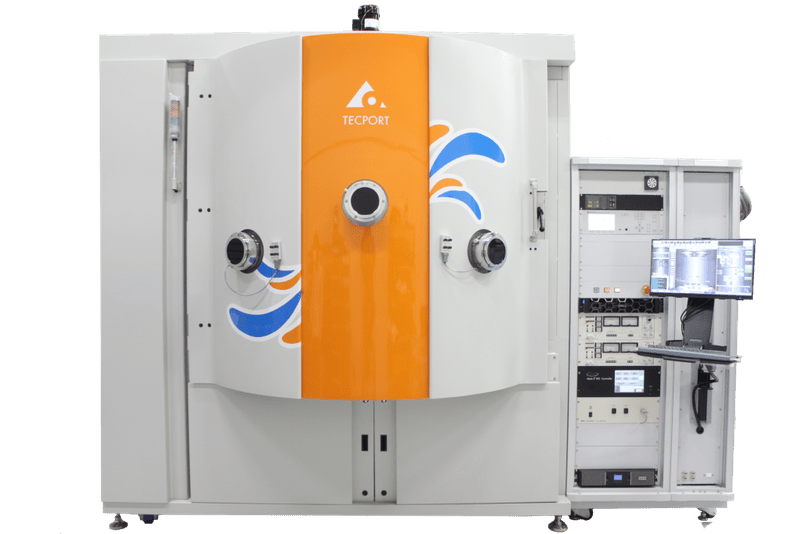
Key geometry and operational variables include:
- Planet Diameter vs. Carrier Radius. Larger planets cover more radial area per rotation but demand greater chamber headroom and higher bearing load capacity.
- Drive Gear Ratios. Non-integer or near-irrational gear ratios prevent parts from repeating identical motion paths, eliminating periodic thickness ripple patterns across the substrate.
- Plane Tilt Angle. Canting the planet plane toward the evaporation source flattens arrival angles across convex surfaces, smoothing out edge roll-off.
- Source Displacement. Strategic off-center source positioning optimizes plume overlap without adding extra mechanical hardware.
Thermal dynamics must be integrated directly into the mechanical design. High-temperature processes cause thermal expansion that alters bearing clearances. Hardware that rotates freely at room temperature can bind at 572°F (300°C). Consequently, material selection, high-vacuum lubrication, and bearing preloads must be engineered for elevated operational states rather than ambient baselines.
Masking, Simulation, and Validation Protocols
While multi-axis motion reduces optical coating thickness error, masking remains necessary for demanding ultra-narrowband or low-loss applications. Correction masks bridge residual non-uniformities, requiring custom profiles mapped specifically to the chamber's physical geometry.
Modern mask development relies on computational ray-tracing models rather than iterative physical machining. By simulating the vapor plume distribution against planetary kinematic paths, software integrates total deposited thickness over time to project a residual error map. Initial mask profiles are CNC-machined directly from this simulated dataset and then validated through empirical test runs.
Process validation follows a structured inspection workflow:
- Multi-Radius Witness Mapping. Position test samples at inner, middle, and outer radial points across a single planet.
- Cross-Planet Verification. Place secondary witness pieces on adjacent planets to confirm azimuthal symmetry across the carrier.
- Direct Component Profiling. Measure production optics directly across their full clear aperture using spectrophotometry or ellipsometry rather than relying solely on flat center witness chips.
- Run-to-Run Drift Tracking. Monitor batch-to-batch variations to decouple mechanical tooling tolerance errors from target erosion or source material depletion.
Targeted process modeling paired with precise optical coating fixturing ensures maximum yield, minimal mask trimming, and repeatable film performance across complex optics.
Customized Tooling Built Around Specific Optics
Tooling must cater directly to specific geometries, chambers, and throughput goals. Tecport Optics constructs systems around this exact engineering philosophy. Our technical team designs planetary fixturing, drive assemblies, and correction masks as core subsystems rather than secondary additions. Platforms like the Symphony Precision configure explicitly around actual part envelopes and uniformity specifications.
We also support existing equipment. Retrofits, rotation upgrades, and redesigned masks restore aging chambers to contemporary tolerances. Explore the comprehensive suite of systems and services within our optical coating equipment portfolio.
If uniformity across curved or large-aperture optics is limiting your yield, connect with our engineering team about tooling designed for your requirements.
Frequently Asked Questions
What is the recommended inspection frequency for planetary tooling bearings?
Inspect bearings and drive couplings on fixed maintenance intervals, typically every few hundred hours of thermal run time. Monitor for mechanical wobble, backlash, and film accumulation on gear teeth. A binding planet triggers uniformity drift well before complete component failure occurs.
Which materials perform best for substrate fixtures in high-temperature optical coating cycles?
Stainless steel and aluminum accommodate standard ambient operations. Heated processes mandate titanium, Inconel, or molybdenum hardware. Match fixture expansion coefficients with bearing designs to preserve stable clearances under intense thermal loads.
Does planetary rotation decrease overall deposition rates?
Rotation itself does not suppress deposition velocity. Correction masks impose rate penalties by intercepting a fraction of the vapor flux. Account for modest throughput reductions whenever geometric masking is integrated.
How are miniaturized optics managed within planetary fixturing?
Compact parts are typically nested inside multi-part carriers mounted into standard planet receptacles. Maintain uniform radial placement for all elements within the carrier.