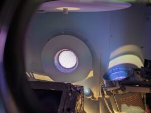
The vacuum atmosphere in an optical coating chamber needs to be free of contaminating vapors such as water, oils, hydrocarbons and other gases because of their relatively high vapor pressures. Deposition processes for optical thin films require vacuum pressures to be reduced to < 10^-6 Torr for metals and semiconductor coating materials, ~10^-5 for oxide compounds. Coating systems are initially pumped to deeper vacua to reduce the concentration of degassing contaminant species to acceptable, namely < 10^-6 Torr.
In addition to outgassing of volatiles from internal surfaces, vacuum leaks of atmospheric gases can compromise the optical integrity and the mechanical and environmental durability of a coating. The presence of leaks, physical and virtual, is evidenced by the inability to reach the required low base pressure established in the previously pumpdown cycle time under optimum conditions. Detecting, diagnosing and correcting vacuum leaks is essential to maintain consistent production flow.
Why Minor Undetected Leaks Can Compromise Thin Film Deposition
A leak near base pressure readings can still influence a deposition run. Continuous atmospheric gas ingress introduces nitrogen, oxygen, and moisture directly that contaminates surfaces and affects growth composition.
Manifestation symptoms appear within measurable parameters:
- Refractive indices systematically deviating from established recipe models
- Uncharacteristic absorption or optical haze appearing in historically clear layers
- Post-venting spectral shifts driven by porous matrices absorbing ambient moisture
- Structural adhesion failures and compounding mechanical stress across thick stacks
- Elevated electron gun instability under previously stable pressure thresholds
- Systematic leak detection proves significantly faster and more economical than iterative process redevelopment, justifying its priority within standard maintenance hierarchies.
Differentiating Physical Leaks From Virtual Leaks and Surface Outgassing
The inability to achieve base pressure is an indication of the existence of physical and virtual leaks. Discovering the source of the leak often requires external diagnostic equipment. A rate-of-rise test establishes the foundational baseline. Isolating the vacuum vessel from pumping infrastructure allows technicians to log internal pressure against elapsed time.
Virtual leaks exhibit distinct behavioral profiles. Trapped volumes residing within blind tapped threads, dual O-ring channels, or improperly vented fastener shafts bleed trapped air slowly and erratically. The resulting pressure curve displays plateaus without stabilizing. Chemical cleaning, vented hardware modification, and optimized fixture architecture resolve these discrepancies without requiring gasket replacement.
A residual gas analyzer provides first-order leak detection by monitoring mass ratios of nitrogen oxygen, water vapor, and hydrocarbons. Comparing mass 28 against mass 32 isolates atmospheric intrusion, where a four-to-one ratio confirms standard air leakage. Elevated mass 18 signals water vapor and routine surface desorption.
Introducing helium shifts mass 4 metrics upward, establishing parameters for subsequent testing phases. Archiving these residual scans alongside pump-down historical records builds a robust diagnostic library, accelerating future evaluations.
Executing Helium Mass Spectrometer Testing Protocols in Vacuum Chambers
A helium mass spectrometer leak detector serves as the industry benchmark for isolating vulnerabilities within high-vacuum equipment. Helium atoms possess high atomic mobility, chemical inertness, and scarce ambient concentration, optimizing signal-to-noise ratios during testing.

Execution demands strict procedural discipline:
- Calibrate against certified leak standards initially, documenting exact instrument response intervals
- Direct tracer application downward from the upper vessel boundary to counter helium buoyancy
- Deploy controlled, momentary bursts via fine-aperture nozzles rather than blanketing the workspace
- Observe complete response delays following each application before transitioning to adjacent joints
- Maintain active ambient ventilation between passes to prevent baseline saturation
**Helium Buoyancy: While spraying helium from top to bottom is standard practice to prevent buoyant helium from floating up to previously tested joints, helium diffuses extremely rapidly in ambient air. Fine control using a micro-metering nozzle and proper room ventilation are equally critical to prevent false positives at adjacent lower joints.
Spot spraying isolates physical leakage sites, whereas enclosure testing determines aggregate system integrity. Comprehensive shrouding yields total system leakage metrics benchmarked against historical service logs. Standard industrial thin film coating platforms maintain baseline integrity within the low 10⁻⁹ atm cc/sec threshold under optimal maintenance, an operational benchmark that belongs in every preventive maintenance ledger.
Isolating Component Vulnerabilities Across Feedthrough Assemblies and Valve Seals
Pressure differential interfaces between the external and internal vacuum environment, such as fixed window seals, electrical, water and gas feedthroughs and rotary mechanical and ferrofluidic drive assemblies, are potential sources of leaks.
High-voltage insulated feedthroughs servicing electron-beam guns and sputter targets experience severe thermal cycling and potential arcing damage over time that can introduce vacuum leaks.
Some examples of vulnerable spots are Isolation valves and poppet closures, elastomeric O-rings lose elasticity over extended service life. Microscopic particulate accumulation on sealing surfaces create paths for leaks that increased clamping pressure cannot overcome. Optical viewports can develop micro-fractures along ceramic frits, and quartz crystal monitor feedthroughs frequently loosen during standard maintenance and handling.
Periodic Monitoring of Pressure Behavior to Maintain High Production Yield
Systematic pumping rate monitoring and leak detection functions as a continuous discipline rather than a reactive emergency protocol. Facilities adhering to scheduled rate-of-rise evaluations, residual gas analyses, and calendar-based seal replacements minimize unplanned downtime. Delaying maintenance until batch failure occurs incurs substantial financial penalties through scrapped substrates and delayed delivery commitments.
At Tecport Optics, our engineers support operators past initial commissioning, providing process optimization, control retrofitting, and specialized operator training. Whether operating proprietary platforms or alternative industry chambers, our technical team is happy to talk through what your pressure data is telling you. When micro-leaks compromise your optical coating outcomes, reach out to our team and let's get your system back to clean, repeatable runs.
Tecport Optics has engineered and supported high-vacuum optical coating systems since 1997, embedding this extensive manufacturing experience directly into system architecture. Chambers incorporate accessible mechanical joints, field-serviceable feedthroughs, and advanced instrumentation that streamline diagnostic procedures.
Frequently Asked Questions
What is the recommended frequency for leak testing a production optical coater?
Standard manufacturing protocols dictate a comprehensive helium evaluation semi-annually alongside monthly rate-of-rise verifications. High-throughput systems operating continuous production shifts benefit from quarterly helium testing. Any vacuum vessel subjected to major mechanical overhaul requires reverification prior to initiating production runs.
How can technicians prevent background helium interference during testing?
Persistent helium accumulation within enclosed spaces can saturate adjacent porous substrates following heavy application. Operators should ensure active ventilation, allow detector baselines to normalize, and administer minimal tracer volumes necessary for detection.
What system leak rate threshold is acceptable for precision optical manufacturing?
Acceptable thresholds vary according to deposition velocities and material sensitivity. Precision facilities typically target system leakage rates below 1 x 10⁻⁸ atm cc/sec. Rate-critical methodologies such as ion beam sputtering demand significantly tighter operational tolerances than conventional thermal evaporation systems.
Can alternative tracer gases replace helium in high-vacuum systems?
Hydrogen and forming gas blends serve as alternative tracers during helium supply shortages. However, these alternatives offer diminished analytical sensitivity and introduce strict safety compliance mandates, preserving helium as the primary standard for high-vacuum optical equipment.