In precision optics manufacturing, thin film deposition and optical coating performance depend heavily on one often-overlooked variable: the shape of the substrate itself. Before a single layer is deposited, the geometry of a part determines how evenly material will land across its surface, and how much engineering effort is needed to ensure deposited uniformity.
Thin Film Deposition: Flat vs. Curved Geometries
Coating a flat optical window and coating a curved lens are fundamentally different uniformity challenges. A flat substrate sits in a predictable, consistent relationship to the deposition source. The flux arriving at any point across its surface is relatively uniform, and thickness control is straightforward.
Curved substrates change that equation entirely. The angle at which vapor flux strikes the surface varies continuously from the center to the edge of a lens. Points near the optical axis receive a different flux density than points near the perimeter.
This thickness variation directly shifts spectral performance, since optical coatings are thickness sensitive. Even a small gradient across a curved aperture can cause wavelength response to shift, reducing the effectiveness of antireflection, bandpass, or high-reflectance designs.
The Thin Film Deposition Variables That Drive Non-Uniformity
Several physical factors compound the challenge with curved or complex substrates:
- Source-to-substrate distance and view factor: As surface curvature increases, different regions of the substrate "see" the source at different angles, creating unequal deposition thickness.
- Line-of-sight flux distribution: Vapor travels in a cosine distribution from the source, creating an inherent non uniform flux distribution. Uniformity distribution correction masks need to be designed and installed.
Substrate Tooling Mountings Can Improve Uniform Distribution
The most widely adopted method for reducing geometric non-uniformity in production environments is the planetary rotation system. In this approach, substrates orbit around the central axis of the chamber (the "sun" rotation) while simultaneously spinning on their own axes (the "planet" rotation).
This dual motion averages out angular and positional variations in the flux. A substrate that would otherwise receive more material on one side gets continuously repositioned relative to the source, smoothing the thickness distribution across the entire surface.
Another approach suitable for batches of small substrates is dome mounting. According to Knudsen's cosine law, when the source is positioned at a vertical distance equal to the diameter of the coating sphere, rotation can produce uniform deposition across the inside of a spherical dome.
For conical or complex curved substrates, planetary rotation alone may not be sufficient. The planetary rotation might need to be around a tilted rotating axis and/or shadowing masks, designed using numerical optimization algorithms, are added to the system to fine-tune local deposition rates.
Research has demonstrated that a well-designed shadowing mask in a planetary system can achieve thickness uniformities better than 99.3% on convex conical substrates. For flat substrates with large apertures, the same approach has pushed uniformity to 99.6%.
When Counter-Rotation Creates New Challenges
Not all planetary configurations produce the same result. Counter-rotating planetary systems, sometimes used to increase chamber capacity for large or oblong substrates, introduce a systematic thickness difference compared to standard planetary rotation.
This error can reduce yield for sensitive, narrow-band coating designs. The takeaway is that the rotation strategy must be matched carefully to both the substrate geometry and the spectral requirements of the coating.
Key considerations when selecting a uniformity correction strategy include:
- Substrate shape (flat, spherical, conical, aspheric) and its curvature-to-aperture ratio
- Choice of standard or counter-rotating planetary motion is appropriate for the part geometry
- The need for shadowing masks or correction shields to fine-tune distribution
- Sensor placement for optical / crystal monitoring sensors, since
crystalmonitors may not accurately represent what a curved part receives
Build Your Thin Film Deposition Process Around Product Dedicated Geometry From the Start
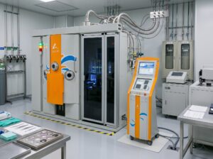
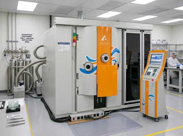
At Tecport Optics, substrate geometry is treated as a primary design input, not an afterthought. Our vacuum coating systems are engineered with planetary bias substrate rotation, as featured in the Rock DLC Coating System, to deliver consistent thickness uniformity across curved, off-axis, and complex optical surfaces. Chamber geometry, fixturing, and motion strategy are specified together, working backward from the required uniformity over the customer's actual aperture.
If your process involves curved lenses, domes, or precision windows with tight spectral tolerances, let's talk. Our engineering team can help you spec a system built around your geometry, not around a generic chamber layout.
FAQ
What other common thin film deposition techniques do engineers use, and how do they differ?
The two major deposition classifications are Physical Vapor Deposition (PVD) and Chemical Vapor Deposition (CVD). PVD methods involve vaporizing a solid material in a vacuum and physically condensing it onto the substrate.
In contrast, CVD techniques use plasma or thermally induced chemical reactions to form dense films on the substrate surface. A key advantage of CVD is its non-line-of-sight nature, which allows it to uniformly coat components with complex shapes.
What primary non-geometric factors are key determinants of final thin film quality?
Beyond geometric considerations, several process parameters significantly influence the quality and physical properties of thin films. These include the substrate temperature and the purity of the vacuum and source material. For instance, a higher deposition rate can improve film purity by minimizing the relative inclusion of gaseous impurities.