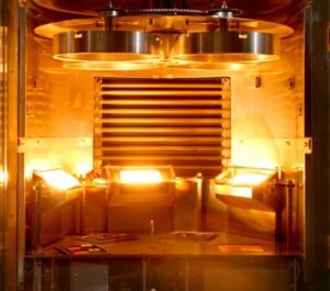
A thin film deposition system chamber is a controlled vacuum environment where optics are cleaned in situ, material is transported from a source to the substrate, and the film is grown with measurable, repeatable results. In precision optics, chamber design is not “just mechanical”; it directly affects contamination risk, thickness uniformity, stress control, and run-to-run repeatability.
Core Components of a Thin Film Deposition Chamber
A chamber is best understood as an integrated set of subsystems that must work together without cross-interference. Typical core elements include:
- Chamber body and access (vessel, door, seals, viewports) designed to minimize particle generation and simplify cleaning.
- Pumping train (roughing plus high vacuum) sized for pumpdown time, base pressure, and process gas handling.
- Vacuum measurement and control (Pirani, cold cathode, ion gauge, valves) that support stable transitions from pumpdown to process.
- Deposition sources (e-beam, thermal, sputter, ion beam, plasma assist) placed for maintainability and line-of-sight control.
- Gas delivery and pumping conductance (mass flow control, manifolds, throttling) that keeps pressure stable during reactive or assisted processes.
- Substrate fixturing and motion (planetary rotation, dome fixtures, tilt) that defines angular distribution and uniformity.
- Monitoring and metrology (quartz crystal, optical monitoring, witness plates) tied to where the film actually grows.
- Shields, liners, and traps (baffles, shuttering, cryo or Meissner elements) used to manage overspray, reduce backstreaming, and control “memory effects.”
Vacuum Integrity and Flange Strategy in Thin Film Deposition
Optical coatings are sensitive to what the chamber contains between “start deposition” and “end deposition.” This includes water vapor, hydrocarbons, and redeposited material from prior runs. Vacuum integrity is not only about achieving a low base pressure. It is about maintaining a stable, clean environment through pumpdown, heat-up, gas introduction (if used), and cooldown.
Flanges and seals are a common leak and contamination pathway, so selection matters. ConFlat (CF) style knife-edge flanges deform a copper gasket to create an ultra-high vacuum capable seal and can tolerate high-temperature bakeout, which is why they are widely used when low outgassing and bake compatibility are priorities.
Elastomer-sealed ISO/KF interfaces can be practical for serviceable lines and foreline plumbing, but they bring higher permeation and temperature limits that can constrain bake and long-term cleanliness.
Leak tightness also depends on details engineers sometimes inherit from “standard designs” without revisiting. It can be bolt patterns and torque access, flange face alignment under thermal load, minimizing trapped volumes (virtual leaks), and keeping weld quality consistent. A chamber that pumps down quickly but drifts during long runs often points back to seal strategy, trapped volume design, or temperature-driven desorption rather than the pump itself.
Chamber Geometry and Uniformity Control
Uniformity is a geometry problem first, and a control problem second. Source-to-substrate distance, angular distribution, and view factors dictate how thickness and optical properties vary across the clear aperture, especially for large optics or steep spectral designs where small thickness gradients shift the wavelength response.
Geometry choices that typically move the needle include:
- Symmetry of source placement relative to the fixture centerline.
- Substrate motion strategy (single-axis rotation vs planetary) to average angular non-uniformities.
- Use of shutters and shields to prevent edge build-up and reduce flake-driven particle events.
- Managing “line-of-sight” paths from hot components to optics, which can drive radiant heating and stress changes.

Uniformity control also depends on where sensors “see” the process. A crystal monitor can be highly repeatable at its location, but still misrepresent what the optic receives if the flux distribution is not well matched. Optical monitoring and witness samples help close that gap, but only when their placement is designed into the chamber geometry.
Materials, Surfaces, and Repeatability
Material selection in a precision optics chamber is mostly about three engineering realities. Outgassing, particulate behavior, and thermal stability. Stainless steels (often in low-carbon variants) are popular because they are robust, weldable, and compatible with a wide range of cleaning and bake practices. Aluminum can be attractive for weight and machinability, but surface treatments, wear points, and compatibility with aggressive cleaning steps must be managed to avoid particles and chemical residues.
Surface condition matters as much as bulk material. Rough interiors, poorly finished welds, and exposed fasteners can become long-term particle sources once coated and thermally cycled. Consistent cleaning and refurbishment workflows work best when the chamber is designed for them.
Repeatability is where all of these choices converge. A practical design review for repeatability often checks:
- Thermal repeatability. Fixture temperature control, radiative coupling, and cooldown time consistency.
- Contamination control. Shield coverage, line-of-sight to pumps, and how overspray is captured.
- Mechanical stability. Fixture runout, rotation consistency, and alignment features that survive maintenance cycles.
- Vacuum stability. Seal selection, trapped volumes, and conductance limits that change with valve position.
- Sensor correlation: Crystal and optical monitoring placement that tracks the part, not just the chamber.
Tecport Optics’ Symphony Precision platform, for example, specifies a 304L stainless steel chamber and an ultimate pressure in the 10^-7 Torr range, reflecting the common industry linkage between chamber construction, vacuum capability, and coating process stability.
Its listed support for multiple deposition techniques, including ion beam sputtering (IBS) and plasma-assisted deposition (PAD), is another reminder that chamber design must anticipate the different gas loads, line-of-sight constraints, and contamination risks each technique introduces.
Specify a Chamber That Protects Optical Performance
A chamber specification is most effective when it is written from the film backward: required uniformity over aperture, allowable scatter and defectivity, stress limits, and the process window needed for production. Tecport Optics has been building and supporting thin-film vacuum deposition systems since 1997, and can help translate coating requirements into chamber architecture, fixturing, vacuum interfaces, and upgrade paths that support repeatable optical output over time.
For IBS-driven applications, Tecport also offers the Navigator IBS system through its partnership with Cutting Edge Coatings. This aligns chamber and monitoring capabilities with high-performance optical coating demands.
If you are evaluating a new build, retrofit, or process transfer, start a chamber design review with Tecport Optics to align vacuum integrity, geometry, materials, and monitoring with your optical specification and production volume.