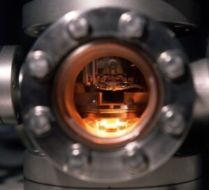
In optical thin-film deposition, an evacuated chamber is rarely an empty space. Advanced vacuum coating technology depends on far more than high-throughput pumping stacks, power supplies, and deposition sources; it relies fundamentally on chamber cleanliness. Residual gas species, specifically trace water vapor and volatile hydrocarbons, can subtly degrade optical coatings. These contaminants, reduce adhesion energy, compromise mechanical and environmental durability, and can lower laser damage thresholds.
For high-precision optics deployed in aerospace, defense, and high-power laser applications, undetected residual chamber contamination represents a significant risk to system performance and coating yield. Controlling these residual gases requires analyzing thin-film growth kinetics, understanding contamination sources and mechanisms, and utilizing real time active diagnostics like Residual Gas Analysis (RGA).
The Molecular Dynamics of Chamber Contamination
At base pressure the deepest vacuum pressure achieved, the vast majority of atmospheric gases have been pumped out. Adsorbed gaseous species remain bound to interior and exterior surfaces, with water vapor comprising the primary ubiquitous residual gas species in unbaked systems. It desorbs slowly from chamber walls, internal fixturing, and optical substrates.
It is necessary to sense and monitor several key contamination sources within the deposition environment:
- Desorbing Water Vapor: Released continuously under vacuum from chamber walls, internal shielding, tooling, and porous coating and substrate materials.
- Hydrocarbon Volatiles: Originating from backstreaming pump fluids, elastomeric O-ring seals, atmospheric pollutants, residual cleaning solvents, and improper handling procedures.
- Atmospheric Ingress: Nitrogen, oxygen, water vapor, and argon signals indicating real micro-leaks across vacuum seals or feedthroughs.
- Process Gas Holdover: Residual working gases retained within gas delivery manifolds and mass flow controllers from previous deposition cycles.
- Particulate Emanation: Particles emitted from evaporation and sputter source materials. Flaking from coating built up on chamber walls and tooling
.
Identifying the sources of contamination is critical for process control. Virtual leaks, caused by trapped gas pockets in threaded fasteners or unvented blind holes, exhibit slow, asymptotic pump-down curves. Atmospheric leaks past feed through seals maintain a constant partial pressure independent of pumping duration. Eliminating these sources via good vacuum coating protocol demands strict attention to details such as chamber surface conditioning and desorption, water vapor trapping, applied heat and plasma scrubbing, uncluttered chamber geometry, and ultra-high-purity source materials.
Influence of Microstructural Growth Nature on Optical Degradation
The energy of arriving adatoms has a large influence on film layer microstructure. High energy is required to provide the high surface mobility required to promote dense amorphous growth microstructure. Surface contaminants describe above interfere with dense adherent growth and can instead result in porous low-density layers.
When these porous films are exposed to ambient atmosphere, capillary action draws atmospheric moisture into the inter-columnar voids. Since the refractive index of liquid water is significantly higher than that of evacuated voids, the effective refractive index of the deposited layer increases. This index shift causes a positive spectral shift, moving the center wavelength of narrowband interference filters and complex multi-layer bandpass coatings longward. Modern vacuum coating technology minimizes this porosity to eliminate environmental drift during humidity changes or thermal cycling.
Hydrocarbon contamination introduces different, equally severe failure modes:
- Interface Degradation: Adsorbed hydro-carbon surface contamination reduces interfacial bonding energy, potentially causing premature failure during MIL-STD environmental testing, tape adhesion tests, or thermal shock cycling.
- Optical Absorption: Hydrocarbon inclusion
screates unwanted absorption bands within the ultraviolet and infrared spectrums. - Laser-Induced Damage Threshold (LIDT) Reduction: Absorbing centers concentrate defect-induced stress under high-fluence pulsed lasers, drastically lowering the LIDT of high-power optical components.
- Nodular Defect Growth: Contaminant seeds from particulate deposition act as nucleation sites for nodular defects. These structural anomalies are sources of pinholes, mechanical stress concentration, and can disrupt local electric field distributions, decreasing laser induced damage thresholds (LIDT).
Pumping Dynamics and Mean Free Path Optimization
Maintaining process cleanliness and purity requires precise control over chamber pressure. According to kinetic gas theory, the time required to form a single monolayer of background gas on a pristine substrate surface is inversely proportional to partial pressure. By lowering base pressure prior to deposition, the background gas arrival rate drops significantly below the adatom deposition rate. This promotes layer growth with high stoichiometric purity and packing density.
Furthermore, advanced vacuum coating technology optimizes the mean free path of the evaporant species as it relates to the deposition technique. At high vacuum levels present in evaporation (~10-6 Torr), the pressures and mean free path ar 2-3 orders of magnitude longer than it is for sputtering deposition. Substrate to source distances are proportionately scaled to minimize the loss of evaporant species energy due to collisions in the residual atmosphere. High arrival energies are required to provide high surface adatom mobility, thereby generating dense, amorphous films without relying on excessive substrate heating.
Achieving these conditions requires at a minimum implementing the following vacuum engineering measures:
- High-Vacuum Pumping Stacks. Cryogenic pumps handle high water-vapor loads, while large turbomolecular pumps efficiently evacuate light gases like helium and hydrogen.
- Cryo-condensation Surfaces. Meissner traps and liquid-nitrogen-cooled shrouds trap residual water vapor during the deposition cycle.
- Low-Outgassing Materials. Utilizing metal seals, ultra-high-vacuum compatible elastomers, and low-outgassing internal fixturing minimizes continuous gas evolution from real and virtual leak sources.
- Load-Lock Systems. Isolating the main process chamber from atmospheric exposure during substrate loading prevents ambient humidity from adsorbing onto internal chamber walls and tooling.
Residual Gas Analysis to Diagnose and Monitor the Chamber Atmosphere Composition
Total pressure gauges, such as inverted magnetron or Bayard-Alpert ion gauges, measure total gas density, but they cannot identify gas composition. Two vacuum systems operating at identical base pressure readings can have fundamentally different chemical environments. One system may contain purely benign nitrogen, while the other suffers from oil backstreaming or high moisture levels.
Residual Gas Analysis (RGA) resolves this diagnostic limitation. Utilizing a quadrupole mass spectrometer, an RGA ionizes residual gas molecules, separates them by their mass-to-charge ratio, and measures their relative partial pressures.
RGA diagnostic spectra enable coating technicians to target and locate the common contamination signatures:
- Mass 18 (Water Vapor). Indicates inadequate chamber bakeout, unconditioned tooling, or atmospheric absorption on surfaces.
- Mass 28 and 32 (Nitrogen and Oxygen). Points to a true mechanical atmosphere leak when observed in a steady four-to-one ratio.
- Mass 44 (Carbon Dioxide). Signals organic residue breakdown or Viton O-ring outgassing under thermal load.
- High Mass Peaks (Over 50). Suggests pump oil backstreaming, solvent residue, hydrocarbon, or grease contamination within the chamber.
Establishing baseline RGA spectra during pump down prior to initiating deposition allows process engineers to quantify chamber purity. Detecting contaminant peaks early prevents lost production runs and supports process qualification under ISO and MIL-SPEC optical standards. Integrating diagnostic instrument monitoring into modern vacuum coating technology turns vacuum quality from an unknown variable into a controllable parameter.
Advanced Systems Engineering for Mission-Critical Thin Films
Inconsistent spectral performance, environmental instability, and durability failures are frequently caused by residual chamber gas contaminants. Maintaining strict control over background contaminant partial pressures is essential for producing resilient, high-precision optical coatings.
At Tecport Optics, we design and build precision optical coating systems engineered around providing and maintaining chamber cleanliness and vacuum integrity. And we can integrate RGA measurement. Our plasma-assisted deposition (PAD), diamond-like carbon (DLC), and plasma-enhanced chemical vapor deposition (PECVD) platforms integrate high-vacuum pumping designs, controlled chamber thermal profiles, and integrated diagnostic instrumentation
Connect with us to evaluate your deposition equipment and discuss targeted solutions for your optical coating processes.
Frequently Asked Questions
How does venting a chamber with dry nitrogen improve vacuum coating efficiency?
Venting with dry nitrogen prevents ambient moisture from adsorbing onto internal surfaces. Eliminating this water layer dramatically shortens subsequent pump-down cycles and reduces baseline contamination.
Can you retrofit a Residual Gas Analyzer onto an existing thin-film system?
Technicians can retrofit an RGA by utilizing an available chamber port with high molecular conductance. An engineer must verify port placement and vacuum pressure ranges to prevent sensor saturation.
How much does cleanroom humidity affect PVD optical coating quality?
Ambient cleanroom humidity heavily forces water adsorption onto exposed substrates and internal fixturing. Implementing controlled dry storage and strict climate control minimizes this initial outgassing load.
How often should operators calibrate or service a Residual Gas Analyzer filament?
Most high-vacuum production environments require formal RGA calibration annually to ensure accurate partial pressure tracking. High-pressure processing or reactive gas exposure accelerates filament degradation, requiring shorter service intervals.